What's New | ||
| ||
R2022x FD01 (FP.2205)
- You can create transitions on vertical alignments for road and railway tracks using a parabolic curve or an arc.
- In the Extract Polyhedral Large Cloud of Points dialog box, a new option is added to the polyhedral extract feature to remove outlier points (computed by the 3D mesher). You can use a slider to choose the percentage of the removed outliers.
- In the Civil Engineering 3D Design app, you can import a predefined city site created in the city apps.
- In the Civil Engineering 3D Design app, the Compound Oval Turn contextual command is now available.
- Three new contextual commands, Switch curve PI composition, Simple Curve Dual PI, and Simple curve dual PI tangency are now available.
- The pattern designer can visualize the pattern group distances between the axes and information about the translational or offset distances of the group axis. New axis displacement capabilities are available to design a compatible and precise pattern.
- A new preference is available for alignments in the Civil Engineering 3D Design app. You can constrain the Sketcher geometry solver to converge to a solution within a customizable time limit.
- You can now customize the description and the visualization of a point through an xml file and a dedicated preferences panel.
- You can now create a sinusoidal or cosinusoidal transition between two curves in compound and reverse configurations. The transition can be created at the start or end of the curve.
- The excavation and filling options are now available in a dedicated panel by
clicking Excavation and Filling
 from the Alignment section of the action bar.
A new attribute to define a vertical offset for tunnel computation is also
available.
 - The following enhancements have been made:
Creating Transitions on Vertical Alignments
Extracting Large Point Cloud into a Polyhedral Mesh
City Connection
Compound Oval Curve
Simple Curve Dual Composition
Linear and Curvilinear Pattern Enhancements
Interruption of the Sketcher geometry solver
Customizing the Display of Point
Sinusoidal and Cosinusoidal Transition Types
Excavation and Filling
Alignment Panel Enhancements
R2022x GA
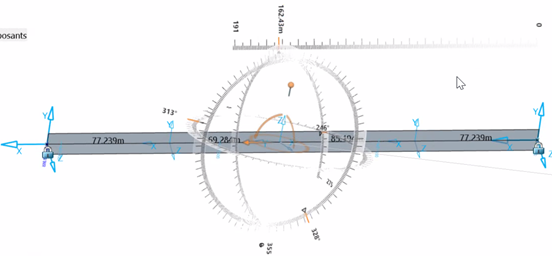
- You can click Play from the Road or Railway section to animate the camera traveling along a 3D curve super-imposed on an existing landscape. The Play options let you customize the display of different parameters.
- When the Display Geolocated Position
 command in the
View section of the action bar
is selected, the Easting and Northing geolocated coordinates replace the display of the
H and V values in the tools palette toolbar or editing panels to define the position of
a geometry.
 - While creating a subgrade type, you can edit the Feature Instantiation Method of object types (OT) with a given discipline (road, railway, platform, or undefined). The content provided in the SubgradeTypicalCrossSections.3dxml is also updated to take benefit of it.
- The support of IFC attributes has expanded. Industry Class Foundation (IFC) is an object-oriented file format used by the AEC industry (architecture, engineering, and construction) to exchange and share information between a set of software.
Alignment Camera Traveling
Visualization and Edition of the Geolocated Coordinates of Geometric Elements
Discipline Definition Available on Cross Sections
AEC PLM Dictionary Update
For more information, see 3DEXPERIENCE Platform User's Guide: 3DSpace Data Model: Unified Typing Reference Dictionary: Packages.
- Optional Installation of Content
-
The app content is no longer automatically installed along with the code. You need to install it yourself, or contact your administrator. For more information, see Install Additional Resources and Install Optional Content. You can also see Installation and Setup: Install: 3DEXPERIENCE Platform: Installing 3DEXPERIENCE Platform Services for the First Time: Installing Services One-by-One: Native Apps: Installing Native Apps: Installing a Native App.
- 3DEXPERIENCE Native Apps Content Reference Guide
- To help you find the reference information you need to use the content delivered along with your app, you can consult the 3DEXPERIENCE Native Apps Content Reference Guide. For more information, see 3DEXPERIENCE Native Apps Content.

