What's New | ||
| ||
R2022x FD01 (FP.2205)
- Die Face Design has been enhanced to better support double-flanges.
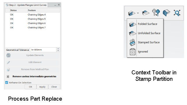
- Process Part Replace: Remove useless intermediate geometries has been added to remove flanges turned useless after a design change.
- Stamp Partition. The context toolbar has been enhanced with:
- Ignored in the list of surface types
- Compute Prehem Surface
- The computation of the unfold has been enhanced to take double-flanges into account.
- Process Generator Wizard: A warning is displayed until metal properties are fully defined in the Die Face Sheet Metal Parameters.
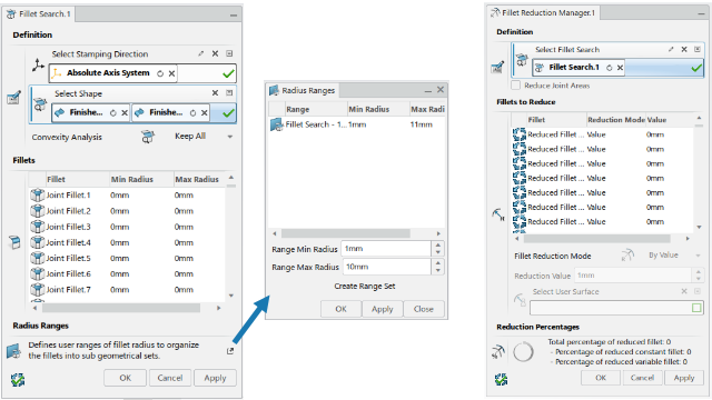
- The commands used to detect fillets and reduce their radius have been replaced by
- Fillet Search finds fillets on a given surface, detects variable fillets on top of constant fillets.
- Fillet Radius Reduction proposes several methods to reduce the radius of fillets.
Support of Double-flanges
Benefits: Double-flange configurations are automatically managed when computing the
unfolded view of a flange in Stamp Partition.
For more information, see
Replacing the Process Part
Creating a Stamp Partition
Using the Process Generator Wizard
Radius Reduction
Benefits: To avoid pinching the sheet of metal between the punch and the die, the
fillets in the die are created by reducing the radius of fillets found in the punch. The
new commands make this process easier and quicker.
For more information, see
Searching Fillets
Reducing the Radius of Fillets
R2022x GA
- You can now use Die Face Design features as result in another app without having access to a Die Face Design license.
- Several commands have been enhanced or created in the Method Plan section to make the update easier.
- The Fill Surfaces command has been renamed into Shut Off Surface.
- Several commands used in the process have been created or enhanced as explained below.
- This command has been enhanced with an auto-pilot mode, proposed by default, that uses min G2 and G1 lengths to compute the extensions.
- The selection in Connect Surface has been simplified.
- This new command fills gaps between surface extensions. In particular, it can fill complex holes.
- Three commands have been added
-
 Boundary Partition
 Variable Offset Curve
 Fillet Based Projected Curve with Angle
- This new command creates a manager feature that analyzes the boundary, and creates children features that are boundaries of different types.
- This new command creates a manager feature to compute extensions in a simple and effective way.
- Several commands have been enhanced or created in the Method Plan section to make the design easier.
- This section has been completed with three commands.
-
 Convert to 3D Spline
 Create a 3D Spline
 Create a 3D Polyline
- Several Die Face Design features have been exposed, to allow the definition of advanced knowledge expert rules to validate a method plan.
Die Face Design Features
Benefits: You can use the features as geometrical results, within any role.
Update of the Process after a Design Part Change
Benefits: The update of the process after a design part change is done quickly, with a
minimum of user interactions.
For more information, see
Assign Geometries to Operations
Using the Detailed Geometry Wizard
Computing All Unfolds
Creating a Cam Direction
Defining a Process Step
Creating a Concept to Detail Link
Creating a Detail to Detail Link
Creating a Detail to Result Link
Managing BReps Links
Replacing the Detailed Process Part
Replacing the Process Part
Performing a Bulk Upgrade
Chaining Edges
Shut Off Surface
Benefits: Shut Off Surfaceis now compatible with Solidworks
XMold.
For more information, see
Filling Holes on Surfaces
Creation of Extension Surfaces
Benefits: The process has been enhanced to be quicker, with fewer interactions and more
stable.
For more information, see
About the Extension Process
Surface Extension
Benefits: The auto-pilot mode makes the creation of extensions quicker and more stable,
and is part of the improvement of the extrapolation process.
For more information, see
Creating a Surface Extension
Connect Surface
Benefits: This command provides three modes to fill holes, automatically or manually,
and is suitable to fill greater areas. It also reduces the number of manual actions,
thus making the process quicker.
For more information, see
Creating a Connect Surface
Fillet Connect
Benefits: This command provides three modes to fill holes, automatically or manually,
and is suitable to fill greater areas. It also reduces the number of manual actions,
thus making the process quicker.
For more information, see
Creating a Fillet Connect
About Fillet Connect
Prehem Surface
Benefits: They make the creation of prehem surfaces easier.
For more information, see
Creating a Boundary Partition
Creating a Variable Offset Curve
Creating a Fillet Based Projected Curve with an Angle
Boundary Analysis
Benefits: This new command is part of the improvement of the extrapolation
process.
For more information, see
Creating a Boundary Analysis Manager
Surface Extension Manager
Benefits: This new command is part of the improvement of the extrapolation
process.
For more information, see
Creating a Surface Extension Manager
Process Design
Benefits: This makes the process design quicker, with fewer interactions .
For more information, see
Administration: Managing Standards
About Die Face Design Standards
Using the Process Generator Wizard
Creating a Process Method Plan
Positioning the Part
Computing the Boundaries of the Flange
Generating the Structure
About Die Face Design Standards
Selection Tools
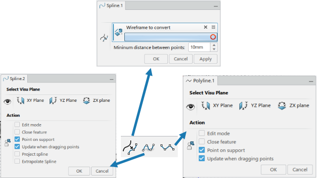
Benefits: The direct manipulation of 3D Splines and Polylines in the 3D area is
improved.
For more information, see
Converting a Wireframe to a 3D Spline
Creating a 3D Spline
Creating a 3D Polyline
Data Model Exposure
Benefits: Die Face Design features are exposed and accessible for knowledge as specific types. You can write
your own Knowledge Expert rules to validate a complete method plan, making the process
of collaborating with suppliers easier. OEMs may delegate the concept process definition
to suppliers, and when they receive it back, they can fully validate it through in-house
knowledge rules.
For more information, see
About Die Face Design and Knowledge