What's New | ||
| ||
R2022x GA
- You can now import and export external data from and to a database.
- In addition, the new command Document Traceability
manages and verifies the status of corresponding documents.

- This enhancement completes the existing file-based system.
- Importing/exporting from and to a database keeps an attachment between the Composites Design 3D shape and the VPM document in the database.
- Document Traceability verifies the synchronization status of documents.
- A laminate can now be defined by a Thickness Ratio.
-

- The Main Stacking Sequence tab has been enhanced.
-
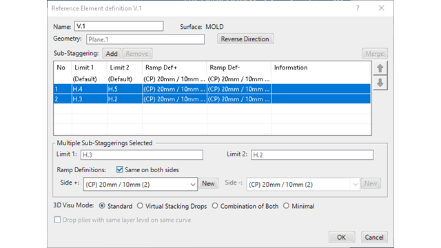
- You can now select several sub-staggerings of a reference element, and edit their ramp definition in one shot, from the dialog box or from the context menu in the 3D area.
-
- You can now change the ramp definition type without losing the offset customization.
- The preview of the centered ramp definitions, and of drop plies with same layer level on same curve has been enhanced and is now correct.
- The user interface has been enhanced.
-
- The dialog box now opens with the size you specified at your last access.
- Ply data information now appears in a dedicated area of the dialog box, to avoid overlap between the texts and the cross section of ply drops.
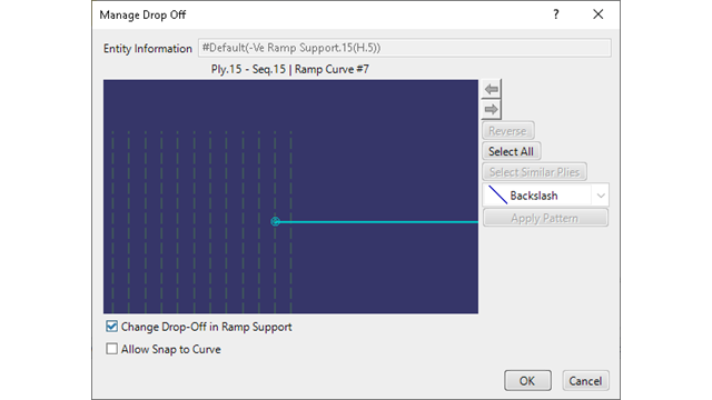
- Several selection commands have been added in Manage Drop-Off.
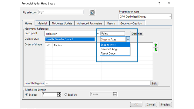
- Two computation options have been added: Constant Angle and About Curve.
-
- Constant Angle: The warp angle at the seed point remains constant along the entire guide curve. This option is useful when the rosette is defined along a curve: The theoretical and actual directions along the curve are identical.
- About Curve: This option models the deposition of unsheared fabric along the guide curve. It is more efficient than using a narrow order of drape region around the curve.
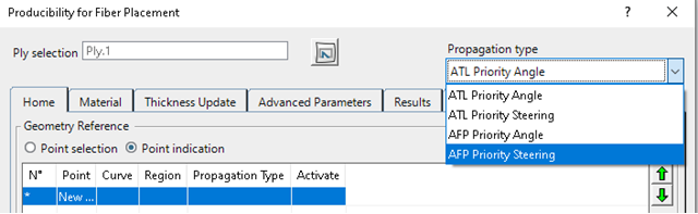
- Propagation types have been modified.
-
- ATL Priority Angle
- ATL Priority Steering
- AFP Priority Angle
- AFP Priority Steering
- A Location Point Creation Wizard has been added to the dialog box.
- It creates location points from a reference point and the number of flattens
per row, or from a pattern.

- The algorithm has been enhanced.
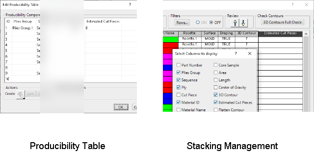
- You can now see the estimated number of cut-pieces from the producibility table and the stacking management table, provided a producibility feature exists.
-
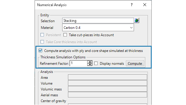
- Two options have been added: Display Normals and Refinement Factor
- When the Compute analysis with ply and core shape simulated at
thickness option is selected, the computation is based on tessellating
entities at surface level and elevating each triangle to the corresponding thickness.
You can now display the normals used for elevating each vertex of the tessellation
triangles. The normals direction and their density help you specify the refinement
factor.
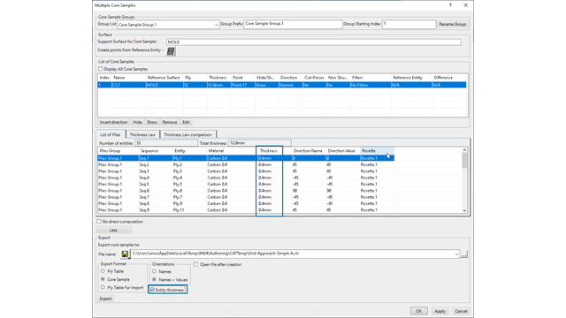
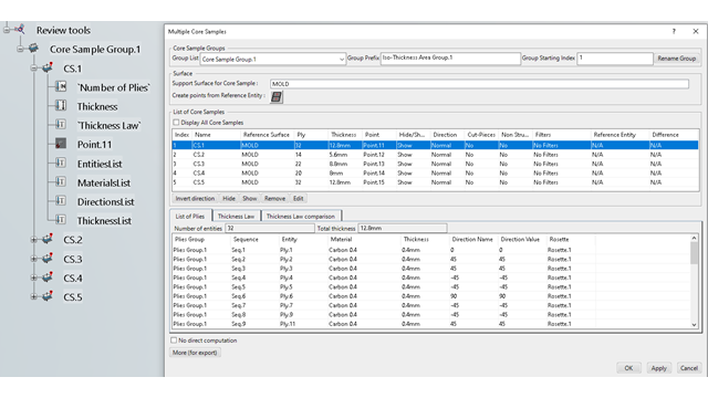
- The table in Multiple Core Samples has been enriched with the individual thickness for impacted entities (Plies/cores/cut-pieces). A check box has been added to export the information.
-
- The computation of the thickness for points lying on butt joints has been corrected.
- You can now create several Core Sample Groups
- You can
- Manipulate each Core Sample Group in the dialog box panel.
- Hide/show a Core Sample Group.
- Name each Core Sample Group.
- Group the identifiers.
- Export the Core Sample Groups individually or as a whole.
Core Sample labels are more readable and movable.
You can select an Iso-Thickness Areas Group as the reference entity, to create a Core Sample Group and its labels from the ITA Group points.
- Material Excess has been enhanced to extend plies in a staggered manner, to create a ramp.
-
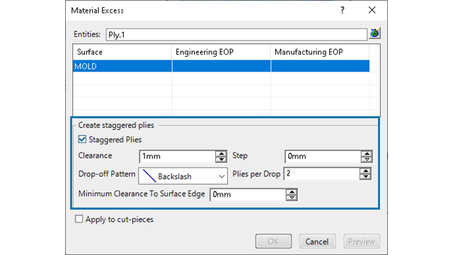
- Two check boxes and one button have been added
-
- Optimize the input junction lines
- Create junction lines in new Geometrical Set
- Edit ITPs to inspect and edit ITPs.
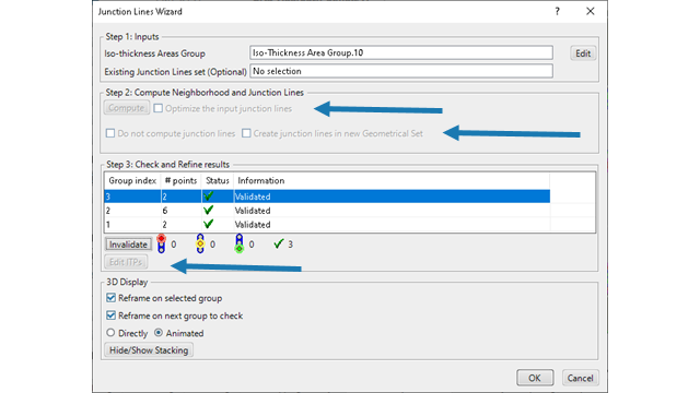
- Quickly corrects small inaccuracies in the Junction Lines Set.
- Ensures that the elevation height/offset equals the thickness specified by the ITP.
- Gathers the junction lines in a Geometrical Set.
- Makes the subsequent creation of a solid from Iso-Thickness Areas easier.
- The error feedback has been enhanced for a better understanding.
-

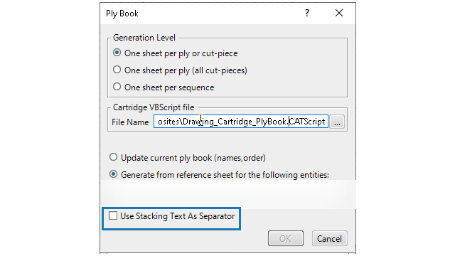
- A check box Use Stacking Text as Separator has been added in the Drafting ply book creation command.
-
Import/Export of External Data
Benefits:
For more information, see
Import, Export, and Manage External Data
Preparing for Import/Export of Files
Manage the Traceability of VPM Documents
Composites Parameters: Adding Laminates
Benefits: You can define a Composites layup as a thickness with various ratios
(percentages) of plies per orientation.
For more information, see
Adding Laminates
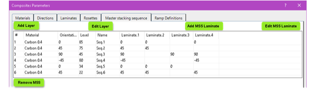
Composites Parameters: Defining a Main Stacking Sequence
Benefits: This enhancement lets you create and improve Main Stacking Sequences directly,
not only by importing/exporting a file.
For more information, see
Defining a Main Stacking Sequence
Grid Panel: Multiple Sub-Staggerings of Reference Element
Benefits: This enhancement reduces the work time.
For more information, see
Edit Several Sub-Staggerings
Ramp Definition: Offset Customization
Benefits: This enhancement reduces the work time and errors.
For more information, see
Specifying a Ramp Definition
Ramp Definition: Preview
Benefits: Correct preview improves productivity and reduces rework.
For more information, see
Specifying a Ramp Definition
Local Drop-Off and Manage Drop-Off
Benefits: The user experience is quicker, and more comfortable.
For more information, see
Creating a Local Drop-Off
Managing Drop-Off
Producibility for Hand Layup: Guide Curve
Benefits: These two options complement the existing Snap to Axes
option to define the warp angle with respect to the guide curve.
For more information, see
Guide Curve Options
Producibility for Fiber Placement: Propagation Type
Benefits: This enhancement provides a baseline tape simulation for the main propagation
methods of Priority Angle and Priority Steering. Subsequent courses are limited to paths
parallel to the preceding course. The simulations support both a conventional axial
material deformation model, and a sheared model supported by experimental systems
supporting CTS (Continuous Tow Shearing).
For more information, see
Start the Producibility for Fiber Placement
Strip Propagation Modes
Flattening
Benefits: This enhancement provides an automatic creation of location points for
flattening.
For more information, see
Use the Location Points Creation Wizard
Splice Plies and Splice Plies from Producibility
Benefits: Performance is improved.
For more information, see
Creating Splice Plies
Creating Splice Plies from Producibility
Estimating the Number of Cut-Pieces
Benefits: Since the ply width often exceeds the width of the material roll, you need to
know whether cut-pieces are required or not. This enhancement automatically provides the
information, from the producibility and the material roll width.
For more information, see
About Estimated Cut-Pieces
Editing Producibility Parameters from the Producibility Table
Displaying Information in the Stacking Management
Numerical Analysis: Refinement Factor and Display Normals
Benefits: You can adapt the accuracy of the numerical analysis to your requirements by
editing the refinement factor, based on the display of the normals.
For more information, see
Performing a Numerical Analysis
A low refinement factor provides more accuracy, but requires more computation time. A higher refinement factor is quicker, but the analysis is less accurate.
Multiple Core Samples: Thickness Information
Benefits: Previously, you could see the total thickness at the core sample point. To
retrieve the individual thickness, you had to retrieve the corresponding material
thickness through several manual steps, even more if multiple core samples were
impacted. This enhancement directly provides the information.
For more information, see
Creating Core Samples
Multiple Core Samples: Thickness on Butt Plies
Benefits: The computed thickness is now correct.
For more information, see
Creating Core Samples
Multiple Core Samples: Identifying Zones
Benefits: You can identify zones with the same thickness, and name them. Design, stress,
and manufacturing departments use this information to communicate.
For more information, see
Creating Core Samples
Editing Core Samples
Material Excess
Benefits: You can drop the plies in staggered manner beyond MEOP to create a
ramp.
For more information, see
About Material Excess
Defining the Material Excess
Iso-thickness Junction Wizard
Benefits: This enhancement
For more information, see
Using the Iso-Thickness Junction Wizard
Solid From Iso-Thickness Areas
Benefits: You can see all the locations of problems on the input junction
lines.
For more information, see
Creating the Solid from Iso-thickness Areas
Ply Book
Benefits: This enhancement lets you create the work instructions directly in the 3D
model, as Stacking Text.
For more information, see
Creating a Ply Book in Drafting