What's New | ||
| ||
R2022x FD01 (FP.2205)
- The Geometry Connection Management command is enhanced with the following capabilities:
-
- While selecting multiple geometries or components, you can now multiselect elements using the selection propagation options from the tools palette.
- You can now trap select multiple surfaces.
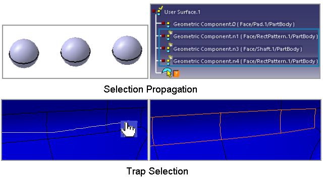
- Using the selection propagation options, you can now quickly select multiple elements in a click.
- Using the Free Hand Selection Trap option, you can drag over the required surfaces to select them.
- You can now create hyperlinks for physical product references and documents.
- You can now position the annotation at the creation itself.
- The System 3D Architecture panel lists the pathway branch and pathway segment feature attributes.
- While using the Attribute Link command, you can now select an object from the search.
- You can now create an FTA thread constructed geometry on the technological result of sheetmetal threaded hole features.
-
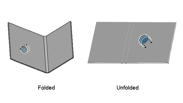
- While creating an offset or aligned view, you can now manage the orientation mode of the offset or aligned section views.
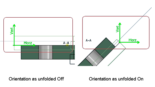
- The Orientation as unfolded option lets you change the
orientation of the FTA section view. To specify this option, select the
Orientation as unfolded check box from
Me
 > Preferences > App Preferences > 3D Modeling > Mechanical Systems
.
> Preferences > App Preferences > 3D Modeling > Mechanical Systems
.
- While transforming a geometry, you can now choose the position of the angle dimension to be maintained.
- While creating an annotation with a leader, using the Leader extremity normal to reference option from the tools palette, you can now create a leader perpendicular to the reference geometry.
-
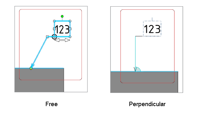
The Leader associativity to the geometry option lets you define the orientation of the leader. To specify this option, go to Me
> Preferences > App Preferences > 3D Modeling > Mechanical Systems.
Selection Propagation and Trap Selection
Benefits:
For more information, see
Managing User Surface in Group of Surfaces
Managing Geometry in User Surface Annotation
Selecting Multiple Surface using Trap
Adding Hyperlinks
Benefits: You can now give quick references to physical products and
documents.
For more information, see
Adding Hyperlinks
Positioning the Annotation
Benefits: You can now quickly position the annotation at the required
location.
For more information, see
Creating a Text with Leader
Creating a Flag Note with Leader
Attribute Browser
Benefits: Using the Attribute Browser, you can filter and sort
the pathway branch and pathway segment feature attributes.
For more information, see
Browsing Attributes: Attribute Browser
Selecting Target Objects from Search
Benefits: Using the search, you can quickly access any data from the database for
selection.
For more information, see
Adding an Attribute Link
Creation of Thread Constructed Geometry
Benefits: Using the Construction Geometry Creation and
Thread Representation Creation commands, you can create thread
constructed geometry for sheetmetal.
For more information, see
Creating Thread Representation
Managing the Orientation Mode of the Section Views
Benefits: Using the Orientation as unfolded check box, you can
now quickly change the orientation mode of the offset and aligned section
views.
For more information, see
Creating an Offset Section View/Section Cut
Creating an Aligned Section View/Section Cut
View from Profile
Managing the Position of Angle Dimensions
Benefits: Using Keep angle range, the position of the angle
dimension is maintained for better readability.
For more information, see
Angle Dimensions
Managing the Orientation of the Annotation Leader
Benefits: While creating an annotation with a leader, press Ctrl
to quickly change the orientation of a leader extremity with respect to the
geometry.
For more information, see
Positioning the Leaders
Leader Associativity to the Geometry
R2022x GA
- A new command, Attribute Browser
 , lets you
browse the attributes for the technological features.
, lets you
browse the attributes for the technological features. - The NOA and tolerancing schema can now be stored in the libraries. You can also instantiate NOA and tolerancing schema stored in the libraries.
- If the annotation view is not parallel to the curved geometry, the leader is positioned perpendicular to the tangent of the curved geometry.
- The weld annotations, surface texture, and edge of undefined shape annotations can now be excluded from the red underline (nonsemantic features).
- To do so, you can specify the preferences under
Non-Semantic at
Me
> Preferences > App Preferences > 3D Modeling > Mechanical Systems
.
- While using the Tolerancing Advisor command, you can now propagate the selection to all the faces or edges based on the selected geometry using the following new commands:
- You can now upgrade the annotation set if the standard version of the annotation set is lower than the standards (ASME/ISO) supported on the current release.
- The selected linear border edge of the nonparametric surface is now treated as a plane and the selected circular border edge of the nonparametric surface is now treated as a cylinder. Based on such selections, the Tolerancing Advisor proposes the commands.
- You can now create the NOAs with no detail or ditto (isolated NOAs). You can also isolate the existing NOAs.
- You can now find the text string from the annotations and replace all the occurrences with the required text string. You can also search for the string in the selected annotations or all the annotations of the selected views.
- You can now specify the margin area percentage while reframing the capture display.
- While displaying the captures or views, the hide or show statuses of the annotations that are not the part of the current capture are not impacted.
- You can now position the annotation leader while creating the annotation.
- The user interface of the Engineering Connection Definition dialog box is now improved.
- You can now select external geometries that are out of the current context, and also create annotations in the assembly context.
Browsing Attributes of the Technological Features
Benefits: Different types of attributes can now be seen are once place.
For more information, see
Browsing Attributes: Attribute Browser
Using Libraries for Storing FTA Resources
Benefits: Support of libraries gives highly improved browse
functionalities.
For more information, see
Storing Note Object Attribute
Create a Catalog of the Tolerancing Schema
Instantiating Note Object Attribute
Tolerancing User Features
Positioning the Leader Extremity on the Curved Geometry
Benefits: In the case of curved geometries, the annotation leader is placed more
precisely.
For more information, see
Positioning the Leaders
Displaying Non-Semantic Annotations without Red Marking
Benefits: You can now quickly select all the faces or the edges of the required
geometries selecting its single face or edge.
Propagating the Selection While Using Tolerancing Advisor
Benefits: You can now quickly select all the faces or the edges of the required
geometries selecting its single face or edge.
For more information, see
Propagation of the Selection in the Tolerancing Advisor
Upgrading the Annotation Set
Benefits: You can upgrade the annotation set standard version to be compatible with the
created one.
For more information, see
Upgrading the Annotation Set
Recognizing Non-Parametric Surfaces
Benefits: You can upgrade the annotation set standard version to be compatible with the
created one.
For more information, see
About Tolerancing Advisor
Removing the Dittos or Details of NOAs
Benefits: You can easily remove the details of the required NOAs.
For more information, see
Creating Note Object Attribute From a Detail/Ditto
Using Find and Replace for Annotations
Benefits: Replacing the text in the annotation is now possible.
For more information, see
Finding and Replacing Text
Reframing a Capture
Benefits: Reframing the captures considering the margin area.
For more information, see
Capture display
Displaying a Capture or a View
Benefits: The modifications in the data due to displaying the captures or views is
avoided.
For more information, see
Displaying a View/Annotation Plane or a Capture
Positioning the Annotation Leader
Benefits: This enhancement helps to place the annotation body at the required position
during annotation creation.
For more information, see
Positioning the Leaders
Enhanced User Interface for Defining Engineering Connections
Benefits: You can now perform actions quickly with less number of clicks. The dialog box
is now simple to interact and has immersive capability, and it is fully compliant with
touch devices.
For more information, see
Creating Annotations in Assembly Context
Edge of Undefined Shape
Benefits: Using the Edge of Undefined Shape command, you can now
create an engineering connection for the edge of undefined shape symbols.